|
Notice: This page contains information for the legacy Phidget21 Library. Phidget21 is out of support. Bugfixes may be considered on a case by case basis. Phidget21 does not support VINT Phidgets, or new USB Phidgets released after 2020. We maintain a selection of legacy devices for sale that are supported in Phidget21. We recommend that new projects be developed against the Phidget22 Library.
|
Mobile Robot (MURVV)
The SBC is unique among Phidgets in that it does not require a connection to a PC to operate. As a result of this, one of the most obvious uses for it is as a part of a mobile system such as a wheeled or legged robot. The idea being that the SBC can act as the brain of the unit and issue commands to the various other pieces all without needing a laptop or desktop computer. With the use of a USB wireless adapter you could even allow a computer connected to the network to send commands to the devices in the robot via the SBC as discussed in the Use Phidgets Wirelessly with the SBC application guide.
Time: Assuming you are fabricating your own chassis something on the order of a week to a week and a half, not including time for parts to ship.
Tools: A welder, a chain splitter, an assortment of screw drivers, a drill press, a wrench or socket wrench (size dependent on hardware used).
Description
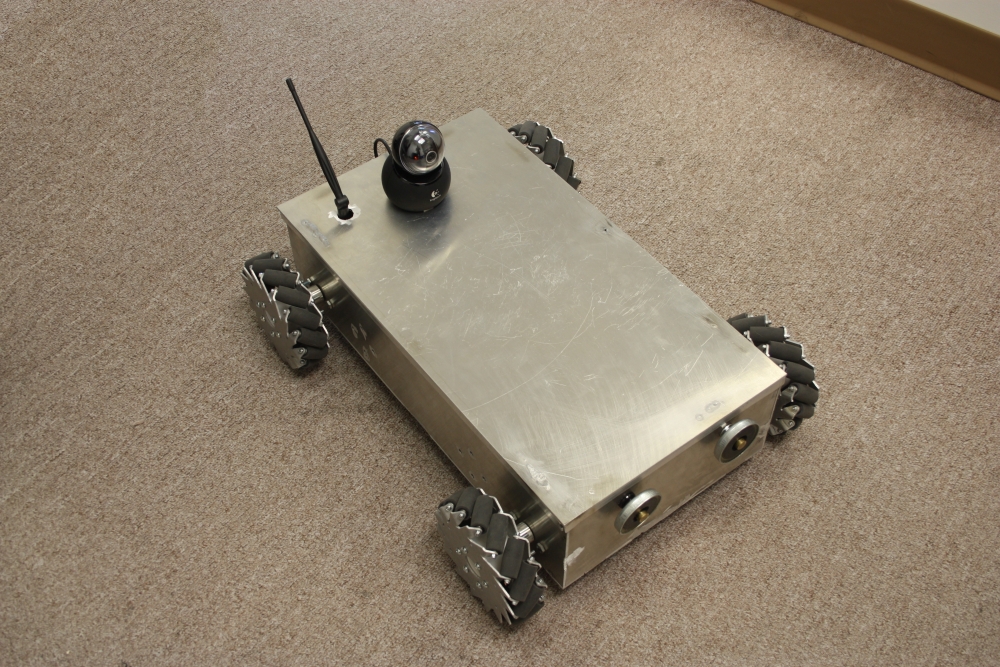
For this project we want to use the SBC as a functional brain for a mobile collection of Phidgets in the form of a wheeled robot. To make things simple we should have independent control of each wheel, this means we do not need any differentials or complex mechanics to split power between wheels. To make manoeuvring a bit easier we also chose to use mecanum wheels. These wheels will allows the robot to move in any direction without actually turning. On the robot we would like to mount a WiFi antenna so that we can transmit information back and forth between the SBC and a PC wirelessly. In addition we want a webcam on board so that we can see what the robot sees and will make remote control easier.
Testing Equipment
As with any Phidgets project the first thing you should do is test all of the devices you will be using. There is no sense building the whole project up only to find that one of the components isn't working. Here is a list of all the Phidgets devices we will be using for this project:
- 1 PhidgetSBC2
- 4 Motor Controllers
- 1 Spatial
- 1 3702 USB WiFi Adapter
- 4 3270 DC Motors w/ 13:1 Gearbox
- 1 3701 Fuse Holder
- 1 3700 Fuse assortment
- 1 Interface kit for taking user input (not part of the actual robot)
The following is a list of non-Phidgets components used:
- Approximately one square meter of 1/8th" aluminium plate or other suitable material
- 8 Sprockets
- 4 Lengths of roller chain
- 4 Steel shafts
- 8 Flange bearings
- 4 Mecanum wheels
- 4 Wheel hubs
- 2 12VDC Lead-acid batteries
- 1 Webcam with pan/tilt functionality
- 1 12VDC output DC-DC converter
- A sheet of acryllic or lexan to separate the motors from the electronics.
Design and Assembly
Chassis, Motors, and Power
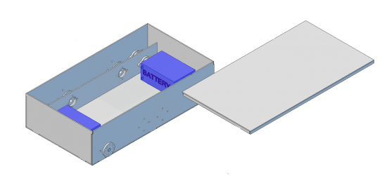
As software developers, we are not really comfortable cutting metal. We prefer to do as much of the work as possible on the computer. For this project, we designed the robot in a relatively inexpensive 3D CAD tool called Alibre. You can download our design files for Alibre here.
We designed the robot to be made from 1/8" aluminum - although there is no reason it couldn't be made from steel. By designing in small interlocking tabs where the sheets of aluminum come together, it's much easier to correctly assemble the robot before welding.
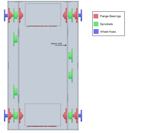
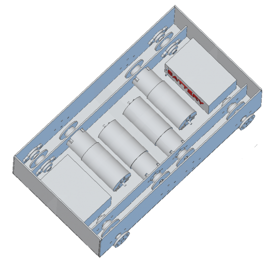
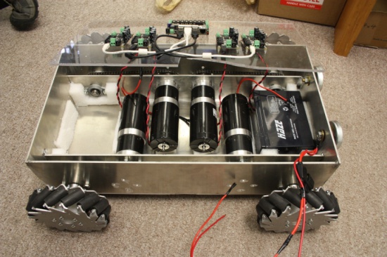
The following pictures show our design for chassis and drive train:
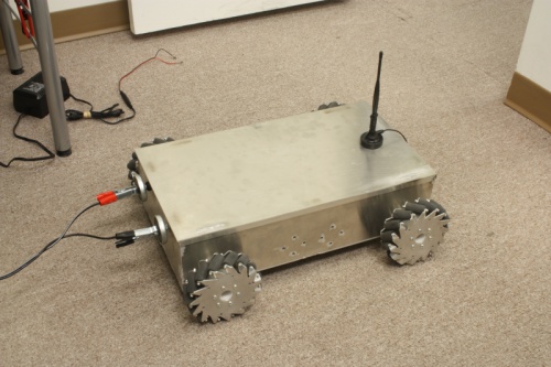
The motors mount to the interior walls. Notice the holes machined into the side of the chassis, they are there to allow easy screwdriver access to the motor mounts:
We welded the frame together using our new TIG welder.
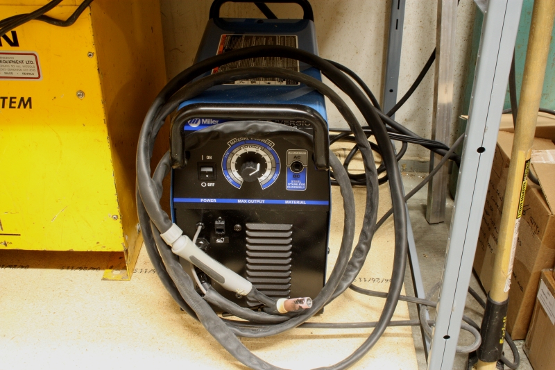
This is the real reason we made the robot out of aluminum - aluminum welding is really hard, and we wanted to try it. In case it wasn't obvious: when you weld, don't do it on a wooden table...

Batteries
We used a pair of 12V, 10Ah lead acid batteries in series to generate 24VDC. We fused the output of the batteries with a 20A fuse. 20 Amps was necessary, even though each of the 4 motors is rated for 2.2 Amps continuous. DC Motors will easily consume much more than their rated current under heavy load or start up. We would occasionally blow the 10 Amp fuse. 15 Amps would probably be sufficient.
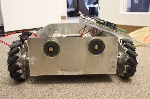
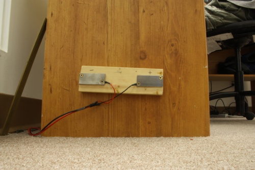
To recharge the batteries we mounted a pair of contacts on the front of the robot so that we wouldn't have to open the lid to recharge. These contacts are actually magnetic welding ground clamps - power is transmitted through the center copper slug, and the spring loaded magnet around the slug applies a constant pressure. We have two steel contacts on the wall connected to the battery charger. We can also clamp the battery charger directly to the copper slugs if someone is using the robot in a different office.
Sprockets and Chains
Timing belts are quieter than chains, but you have to order exactly the right size. Chains are able to transmit a massive amount of torque, and the length can be (relatively) quickly changed.
When you are trying to decide how much chain you will need there is a simple formula you can use. For our robot we used sprockets that were all the same size, this leads to a gear ratio of 1:1 so there is no increase in torque or speed but it also simplifies the math behind chain length calculation. To calculate the length of chain you will need to encompass 2 sprockets the following formula is used:
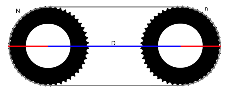
Where N and n are the number of teeth on the respective sprockets, K is N-n, and X is the chain pitch. One pitch is one link of the chain, or the distance between 2 adjacent pins.
For example:
The chain we used has a pitch of 0.25". Our sprockets had 28 teeth each, a radius of 1", and on the short side were 4" apart center to center. This means that the length of chain required was
or 60 pitches. To calculate the length in inches multiply that number by the chain pitch, 60 * 0.25 = 15". When you are cutting chain to the appropriate length a chain splitter can be helpful. The chain splitter we had though was not very effective and we just ended up using a hammer and nail to punch the pins out. Either way this can be a time consuming task so make sure you have the lengths correct before you connect it all up!
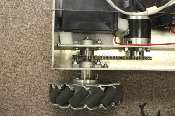
Something we did not do but we discovered is extremely useful while mounting the chains is that if you design the mounting holes for the motor to be slotted it is very easy to mount the chain and then tension it by simply sliding the motor in and out of position before tightening the mounting bolts down:

Shafts and Bearings
We used 4 12mm shafts that were 100mm long each. Each shaft has 2 flange bearings which hold it in place and reduce friction when the shaft is spinning.
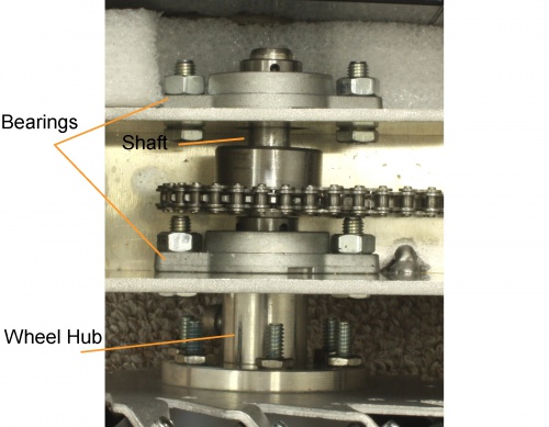
Electronics
We cut a sheet of acrylic to sit on top of the motors and act as the mounting point for all of the electronics.
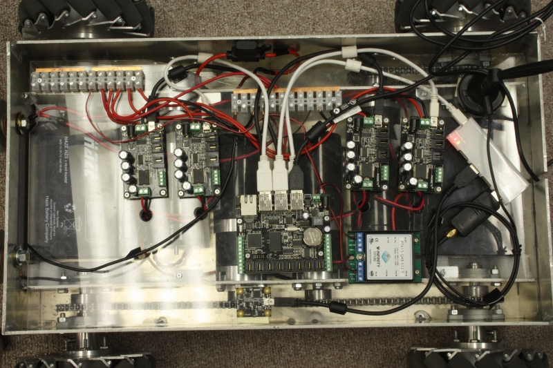
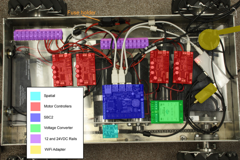
Since we have wired the 2 12V batteries in series, we have a 24VDC output. This is good since the motors we are using are 24V motors, however this is also a problem since the SBC runs on 12V. To solve this, we have included a 12V output DC-DC converter (highlighted in green) so that our system has both a 24V and 12V rail.
Software
Since the SBC is acting as the brain for this project, most of the interactions with the Phidgets will be taken care of by it. However, unless you are intending the robot to be autonomous, some sort of connection to an external PC must be made so that you can control it. Ultimately this means that we will have both a program running on your computer which takes user input, and a program on the SBC which controls the motor controllers etc... Communication between the two programs will be handled using the Phidget Dictionary.
PC Side
The PC handles taking input from the user and translating it into a set of desired motor speeds, displaying some information and controls, and viewing the webcam feed. Since the mecanum wheel allow must be controllable on 3 separate axes (x, y, and a rotational one) the most popular method of controlling this style of robot is a twin joystick style with one joystick controlling x and y motion and the other joystick controlling rotation. We ended up using a single joystick that had an additional axis built into it, but in practice anything that allows you to control position in 3 distinct channels would work. The joystick we used connects directly to the analog input ports on a 1018, this is nice since it makes the code for taking input from the joystick easy.
Take Input
void controller_SensorChange(object sender, Phidgets.Events.SensorChangeEventArgs e)
{
    JoystickDrive((controller.sensors[joyStickXAxisIndex].RawValue - xMid) / 2000.0,
                  (controller.sensors[joyStickYAxisIndex].RawValue - yMid) / 2000.0,
                  -(controller.sensors[joyStickZAxisIndex].RawValue - zMid) / 1500.0);
}
This function collects data from each channel of the joystick every time there is a change in one of the channels and then sends it off to a function which converts the joystick position into a magnitude, direction (x and y vector) and a rotation (the final axis of the joystick). The math done on each sensor value is to center it around 0 rather than 500 (or 2000 in the case of RawValue). The 3rd channel of our joystick has more limited range than the other two, hence we only divide by 1500, not 2000.
Convert Input
The function that converts this data into something usable looks like this:
void JoystickDrive(double x, double y, double z)
{

	//Dead Space
	double xyDeadSpace = 0.1;
	double zDeadSpace = 0.25;

        //Check that the position is outside the deadspace
	double newx = (Math.Abs(x) - xyDeadSpace) * (xyDeadSpace+1);
	if (newx < 0) newx = 0;
	x = (x < 0) ? -newx : newx;
	double newy = (Math.Abs(y) - xyDeadSpace) * (xyDeadSpace + 1);
	if (newy < 0) newy = 0;
	y = (y < 0) ? -newy : newy;
	double newz = (Math.Abs(z) - zDeadSpace) * (zDeadSpace + 1);
	if (newz < 0) newz = 0;
	z = (z < 0) ? -newz : newz;

	x = Limit(x); //these values should saturate at 1
	y = Limit(y);
	z = Limit(z);

	double magnitude = Math.Sqrt(x * x + y * y);
	double direction = Math.Atan2(x, y);
	double rotation = z;

	if (magnitude == 0)
		direction = 0;

	//Into degrees
	direction = direction * 180.0 / Math.PI;

	if (gyroLocked)
	{
		direction -= heading;
		direction += headingLockPoint;
	}

	if (direction < 0)
		direction += 360;
	if (direction > 360)
		direction -= 360;

	MecanumDrive(magnitude, direction, rotation);
}
The "dead space" from lines 5 and 6 is important, it negates any very small movements that are often caused by slop in the joystick's mechanical components.
Calculate Wheel Speeds
Once we have a direction, heading, and rotation we need to calculate how much power to give each motor in order to achieve the desired motion. In a normal vehicle this would be fairly straight forward but with mecanum wheel there is a bit of work involved.
void MecanumDrive(double magnitude, double direction, double rotation)
{
	//Limit limits magnitude to 1.0
	magnitude = Limit(magnitude);

	// Normalized for full power along the Cartesian axes.
	magnitude = magnitude * Math.Sqrt(2.0);

	// The rollers are at 45 degree angles.
	double dirInRad = (direction + 45.0) * Math.PI / 180.0;
	double cosD = Math.Cos(dirInRad);
	double sinD = Math.Sin(dirInRad);
	double[] wheelSpeeds = new double[4];

	wheelSpeeds[0] = sinD * magnitude + rotation;
	wheelSpeeds[1] = cosD * magnitude - rotation;
	wheelSpeeds[2] = cosD * magnitude + rotation;
	wheelSpeeds[3] = sinD * magnitude - rotation;

	//Only if any are > 1.0
	Normalize(wheelSpeeds);

	frontLeftSpeed = (wheelSpeeds[0] * m_maxOutput * frontLeftDir);
	frontRightSpeed = (wheelSpeeds[1] * m_maxOutput * frontRightDir);
	rearLeftSpeed  = (wheelSpeeds[2] * m_maxOutput * rearLeftDir);
	rearRightSpeed = (wheelSpeeds[3] * m_maxOutput * rearRightDir);
}
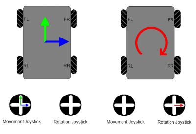
The first thing that might appear strange here is the magnitude = magnitude * Math.Sqrt(2.0); line. This is an artifact of how joysticks function. To better understand, have a look at the following diagram:
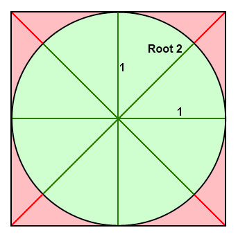
Since joysticks have a circular range of motion you run into the problem that you will only reach a maximum X or Y value when you are along the X or Y axis. So if you are on any heading other than 0, 90, 180, or 270° you will never be able to travel at full speed. By scaling the magnitude by the square root of 2 you can be sure that you will reach full speed on all headings, and since the wheel speeds all get normalized later you don't have to worry about exceeding the maximum velocity the motors can achieve.
When calculating the direction and speed to spin the wheels at based on the joystick input there are two common ways to represent a point on a 2d plane: Cartesian coordinates, and polar coordinates. To generalize our code to any controller we have used polar, though the algorithm can perhaps be more easily understood if we instead look at it in the more traditional Cartesian coordinate system. Let's again use the case of twin joysticks being used to control the robot:
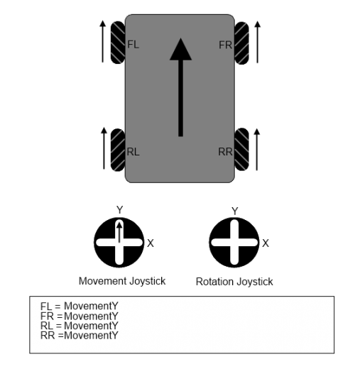
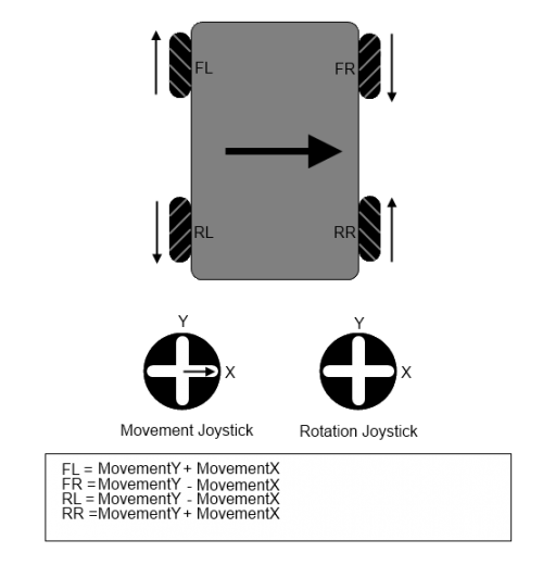
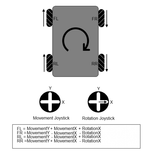
By summing force vectors for each of the primary directions we can get a resultant vector that will be of the right magnitude and direction. Note that the diagram only shows directions for positive values of X, Y, and Z (MovementX, MovementY, and RotationX). For negative values the arrows would simply be reversed, the math stays the same. The last thing we do is normalize the values so they are all between a magnitude of 0 and 1, scale them by the maximum motor speed so they are a proportionate percentage of max velocity, and add in the direction modifier:
Normalize(wheelSpeeds);

frontLeftSpeed = (wheelSpeeds[0] * m_maxOutput * frontLeftDir);
frontRightSpeed = (wheelSpeeds[1] * m_maxOutput * frontRightDir);
rearLeftSpeed  = (wheelSpeeds[2] * m_maxOutput * rearLeftDir);
rearRightSpeed = (wheelSpeeds[3] * m_maxOutput * rearRightDir);
The frontLeftDir, frontRightDir etc... modifiers are used to invert the values for the motors which are facing the opposite direction. Remember that two of the motors are facing one way and the other two are facing the other way. This means that we need to invert the values since otherwise the motors will appear to work in reverse (think of screwing a bolt in from above versus below the bolt).
Full Code
You can download the full Visual Studio project here:
This project includes code to interface with the webcam. You can learn more about interfacing with webcams in the USB Webcam Primer.
SBC Side
All the code on the SBC does is take the information from the computer and set the speed of the motors to the appropriate level. Communication between the SBC and the PC is done by using the Phidget Dictionary. Most of the code on the tank is just taking care of opening and registering handlers for all the various devices being used. The important bits are the main loop:
while(1)
{
	usleep(100000); //100 ms
	gotSet++;

	//We haven't had a set in > 500ms!! Stop motors
	if(gotSet >= 5)
	{
		CPhidgetMotorControl_setVelocity(motoControl[0], 0, 0);
		CPhidgetMotorControl_setVelocity(motoControl[1], 0, 0);
		CPhidgetMotorControl_setVelocity(motoControl[2], 0, 0);
		CPhidgetMotorControl_setVelocity(motoControl[3], 0, 0);
	}
}
Here we want to make sure we have some way of stopping the motors if we apparently lose connection to the controller. And the dictionary handler which listens for new entries and grabs the new values as they come in.
Download
You can download the full code here:
Finished!
