Controlling an I2C Display: Difference between revisions
(Created page with "==Introduction== link=https://wwwdev.int.phidgets.com/docs/images/f/f5/ADP0001_0_169.jpg|thumb| 450px|<center>[https://www.phidgets.com/?prodid=1354 I2C Adapter Phidget (ADP0001_0)] The [https://www.phidgets.com/?prodid=1354 I2C Adapter Phidget] allows you to interface with a wide range of I2C-compatible devices, including sensors, displays, and more. In this project, we will use it to control a 14-segment alphanumeric display. ===Steps===...") |
No edit summary |
||
| (One intermediate revision by the same user not shown) | |||
| Line 1: | Line 1: | ||
<metadesc>A step-by-step example writing code to interface a sensor with the ADP0001.</metadesc> | |||
==Introduction== | ==Introduction== | ||
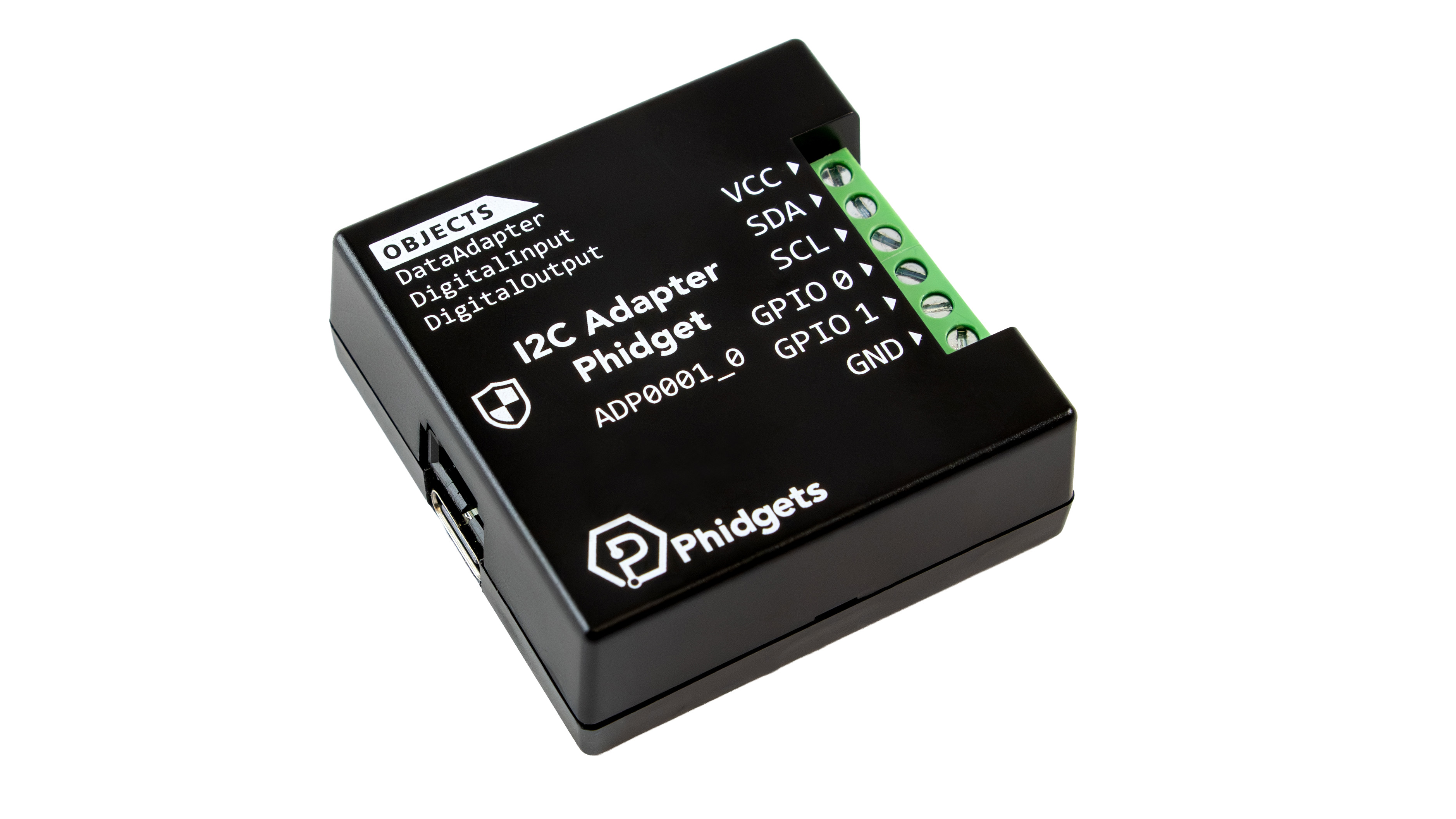
[[Image:ADP0001_0_169.jpg|link=https:// | [[Image:ADP0001_0_169.jpg|link=https://cdn.phidgets.com/docs/images/f/f5/ADP0001_0_169.jpg|thumb| 450px|<center>[https://www.phidgets.com/?prodid=1354 I2C Adapter Phidget (ADP0001_0)]]] | ||
The [https://www.phidgets.com/?prodid=1354 I2C Adapter Phidget] allows you to interface with a wide range of I2C-compatible devices, including sensors, displays, and more. | The [https://www.phidgets.com/?prodid=1354 I2C Adapter Phidget] allows you to interface with a wide range of I2C-compatible devices, including sensors, displays, and more. | ||
| Line 21: | Line 23: | ||
==Configuration Parameters== | ==Configuration Parameters== | ||
[[Image:Adp0002_an_productpage2.png|link=https:// | [[Image:Adp0002_an_productpage2.png|link=https://cdn.phidgets.com/docs/images/2/26/Adp0002_an_productpage2.png|thumb|<center>Product page features</center>]] | ||
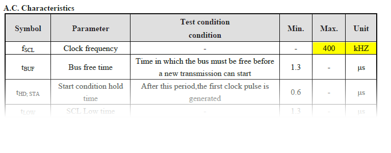
[[Image:I2C_Sensor_Freq.png|thumb|link=https:// | [[Image:I2C_Sensor_Freq.png|thumb|link=https://cdn.phidgets.com/docs/images/5/59/I2C_Sensor_Freq.png|<center>VK16K33 datasheet (Page 29)</center>]] | ||
During this step, we are looking for the following information: | During this step, we are looking for the following information: | ||
* Supply Voltage | * Supply Voltage | ||
| Line 39: | Line 41: | ||
[[Image:Adp0002_an_flow.png|link=https:// | [[Image:Adp0002_an_flow.png|link=https://cdn.phidgets.com/docs/images/a/a8/Adp0002_an_flow.png|750px|center]] | ||
<center>''Adapted from datasheet (page 26)''</center> | <center>''Adapted from datasheet (page 26)''</center> | ||
| Line 58: | Line 60: | ||
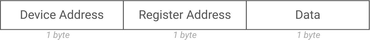
I2C devices typically expect the following format: | I2C devices typically expect the following format: | ||
[[Image:Adp0002_an_typicalcomms3.png|link=https:// | [[Image:Adp0002_an_typicalcomms3.png|link=https://cdn.phidgets.com/docs/images/2/29/Adp0002_an_typicalcomms3.png|600px]] | ||
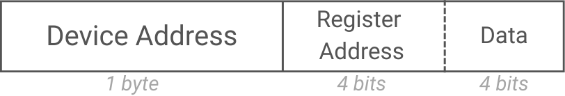
The VK16K33 instead expects the following format, where the register address and data is combined into a single byte: | The VK16K33 instead expects the following format, where the register address and data is combined into a single byte: | ||
[[Image:Adp0002_an_VK16K33comms4.png|link=https:// | [[Image:Adp0002_an_VK16K33comms4.png|link=https://cdn.phidgets.com/docs/images/c/c5/Adp0002_an_VK16K33comms4.png|400px]] | ||
===Power On Steps=== | ===Power On Steps=== | ||
| Line 69: | Line 71: | ||
The system clock (oscillator) is managed by register '''0x20''': | The system clock (oscillator) is managed by register '''0x20''': | ||
[[Image:I2C_Sensor_SysClock.png|link=https:// | [[Image:I2C_Sensor_SysClock.png|link=https://cdn.phidgets.com/docs/images/d/d7/I2C_Sensor_SysClock.png|center|850px]] | ||
<center>''VK16K33 datasheet (page 7)''</center> | <center>''VK16K33 datasheet (page 7)''</center> | ||
| Line 77: | Line 79: | ||
====Set Dimming Register==== | ====Set Dimming Register==== | ||
Dimming is managed by register '''0xEF''': | Dimming is managed by register '''0xEF''': | ||
[[Image:Adp0002_an_dimmingreg.png|link=https:// | [[Image:Adp0002_an_dimmingreg.png|link=https://cdn.phidgets.com/docs/images/3/30/Adp0002_an_dimmingreg.png|center|850px]] | ||
<center>''VK16K33 datasheet (page 25)''</center> | <center>''VK16K33 datasheet (page 25)''</center> | ||
| Line 95: | Line 97: | ||
====Set the Write Address==== | ====Set the Write Address==== | ||
The display RAM is 16 bytes and begins at address '''0x00''': | The display RAM is 16 bytes and begins at address '''0x00''': | ||
[[Image:Adp0002_an_ram.png|link=https:// | [[Image:Adp0002_an_ram.png|link=https://cdn.phidgets.com/docs/images/b/bd/Adp0002_an_ram.png|center|750px]] | ||
<center>''Datasheet page 10''</center> | <center>''Datasheet page 10''</center> | ||
| Line 110: | Line 112: | ||
We can set the voltage to 3.3V, the frequency to 400kHz, and the address to 0x70. We can then queue up the commands we determined in the previous step. | We can set the voltage to 3.3V, the frequency to 400kHz, and the address to 0x70. We can then queue up the commands we determined in the previous step. | ||
[[Image:I2C_Sensor_ControlPanel2.png|link=https:// | [[Image:I2C_Sensor_ControlPanel2.png|link=https://cdn.phidgets.com/docs/images/c/c9/I2C_Sensor_ControlPanel2.png|center]] | ||
Since we have not sent any data to the RAM yet, the segments are uninitialized, with some on and some off: | Since we have not sent any data to the RAM yet, the segments are uninitialized, with some on and some off: | ||
[[Image:I2C_Sensor_UnInit.png|800px|link=https:// | [[Image:I2C_Sensor_UnInit.png|800px|link=https://cdn.phidgets.com/docs/images/8/8c/I2C_Sensor_UnInit.png]] | ||
===Display Steps=== | ===Display Steps=== | ||
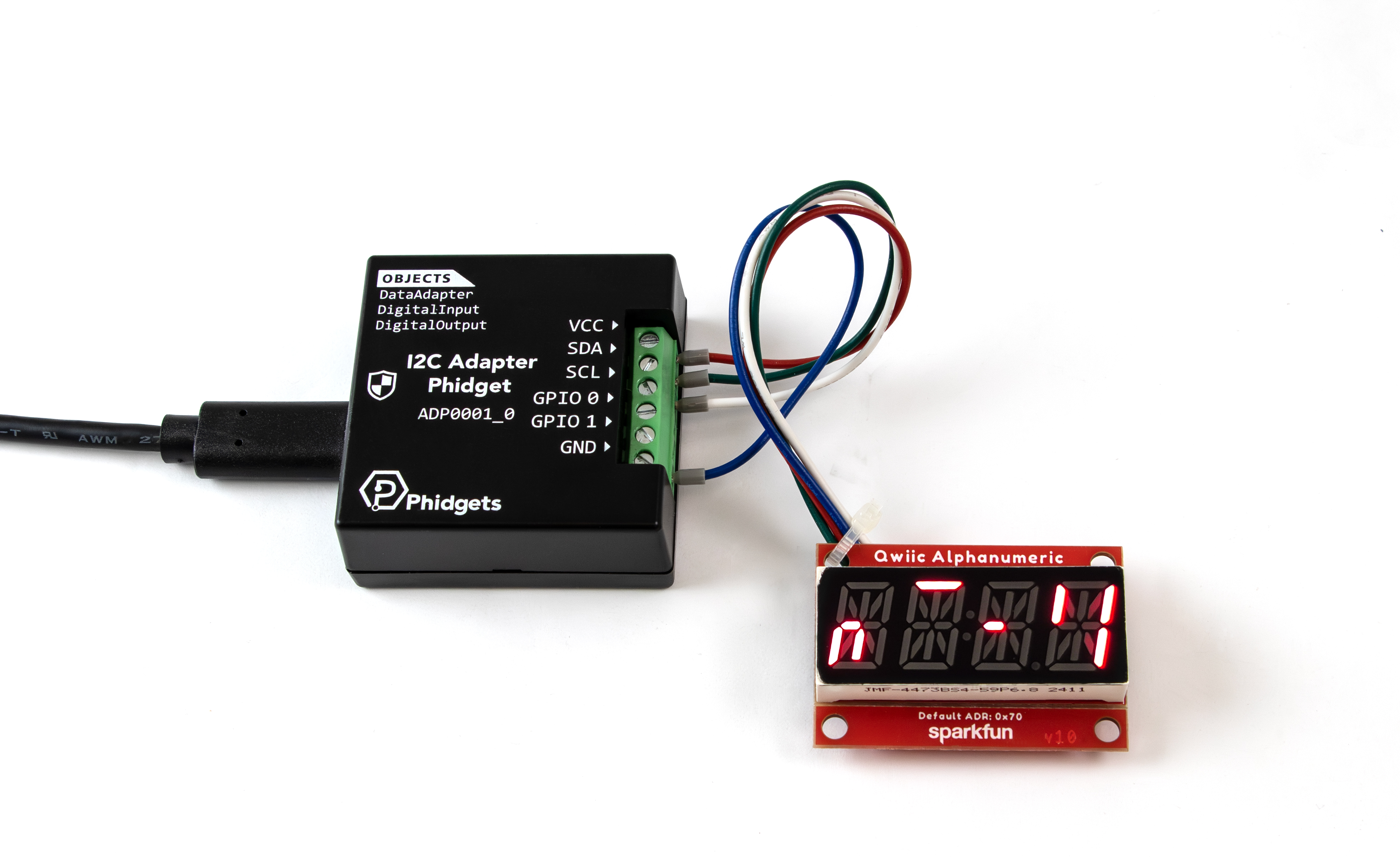
| Line 129: | Line 131: | ||
[[Image:I2C_Sensor_Phid.png|800px|link=https:// | [[Image:I2C_Sensor_Phid.png|800px|link=https://cdn.phidgets.com/docs/images/c/cd/I2C_Sensor_Phid.png]] | ||
===Reading Display RAM=== | ===Reading Display RAM=== | ||
This display also supports reading the RAM, so you can programmatically know what's currently showing on the display. For most devices, this is as simple as providing the proper command and specifying a number of expected reply bytes. In this case, the device is expecting a stop condition in between the command and the data, as shown by the 'P' in the third block in this diagram: | This display also supports reading the RAM, so you can programmatically know what's currently showing on the display. For most devices, this is as simple as providing the proper command and specifying a number of expected reply bytes. In this case, the device is expecting a stop condition in between the command and the data, as shown by the 'P' in the third block in this diagram: | ||
[[Image:I2C_Sensor_Read.png|850px|link=https:// | [[Image:I2C_Sensor_Read.png|850px|link=https://cdn.phidgets.com/docs/images/b/b4/I2C_Sensor_Read.png|center]] | ||
<center>''From page 23 of the datasheet''</center> | <center>''From page 23 of the datasheet''</center> | ||
Latest revision as of 22:57, 12 February 2026
Introduction
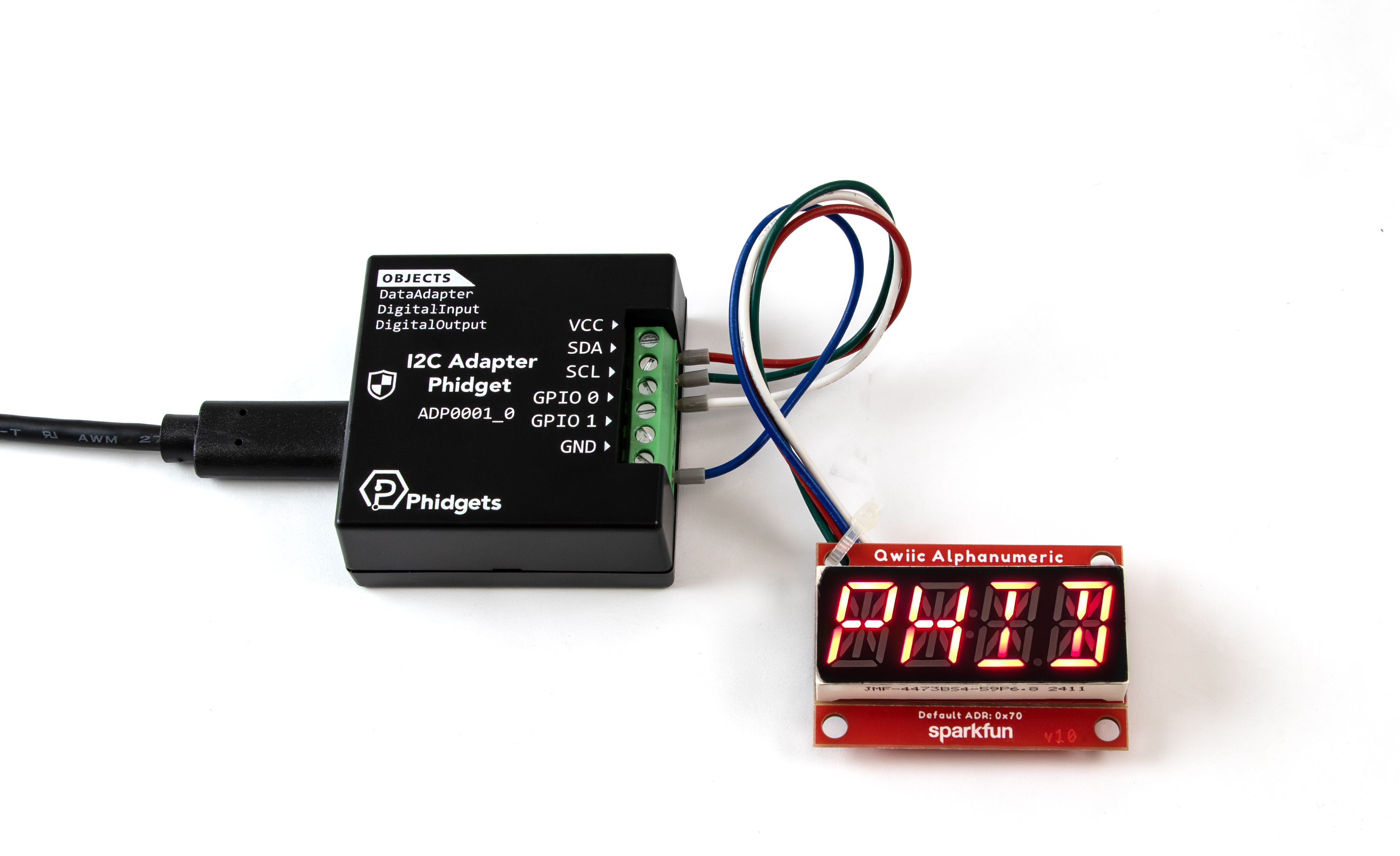
The I2C Adapter Phidget allows you to interface with a wide range of I2C-compatible devices, including sensors, displays, and more.
In this project, we will use it to control a 14-segment alphanumeric display.
Steps
To complete this project, we will work through the following steps:
- Determine the device's basic configuration parameters
- Identify the sequence of commands expected by the device
- Test the device using the Phidget Control Panel
- Create a custom program.
Resources
Information from the following resources will be referenced throughout this project.
Demonstration
Configuration Parameters
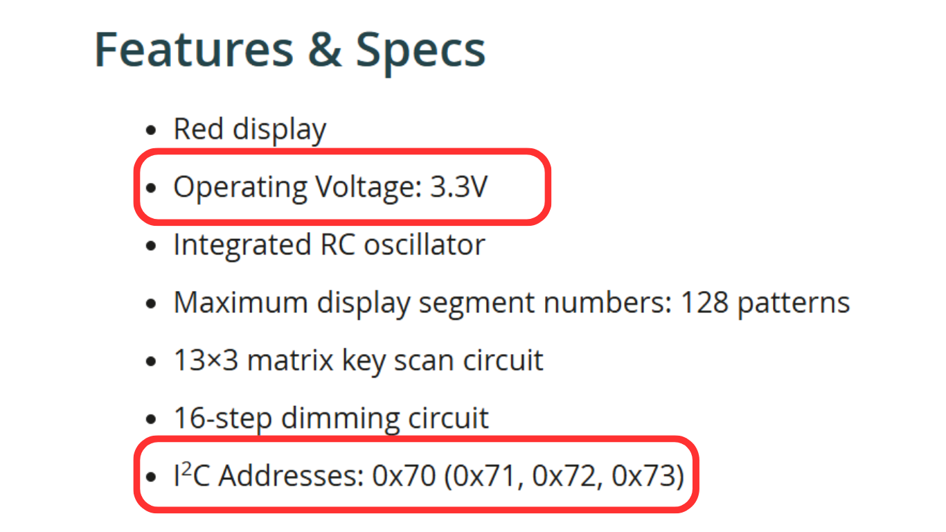
During this step, we are looking for the following information:
- Supply Voltage
- Communication Frequency
- Device Address
This information is typically found using the device's product page and/or any relevant datasheets. Based on these resources, we will use the following parameters:
- Supply Voltage: 3.3V*
- Communication Frequency: 400kHz
- I2C Address: 0x70
*The datasheet specifies an operating voltage of 4.5-5V, however, this applies only when the chip is powered directly. The breakout board includes an onboard 3.3V to 5V boost circuit, which provides the required operating voltage for the chip.
Command Sequence
Next, we need to determine the sequence of commands the device is expecting. The VK16K33 datasheet provides flowcharts that we can use to create a list of actions:
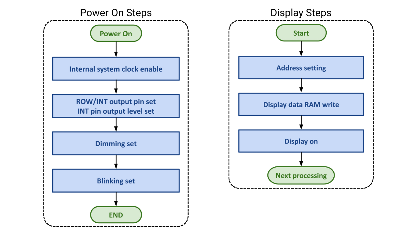
Based on the flowcharts, our list of actions should look like this:
Power On Steps:
- Enable the internal system clock
- Set the dimming register
- Set the blinking register
* The ROW/INT step is ignored because the feature is not being used.
Display Steps
- Set the write address
- Send the data to display
- Turn on the display
Writing to VK16K33 Registers
I2C devices typically expect the following format:
The VK16K33 instead expects the following format, where the register address and data is combined into a single byte:
Power On Steps
Enable the System Clock
The system clock (oscillator) is managed by register 0x20:
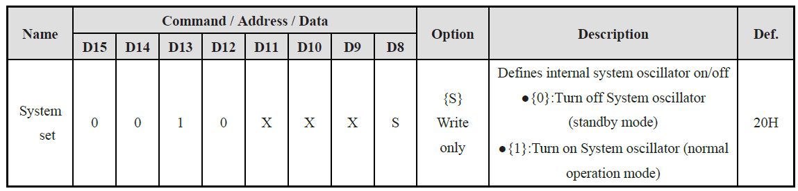
This register only has one relevant bit, the S bit in position D8. By sending the command 0010 0001 (0x21 in hexadecimal), the system clock will be enabled. Bits marked with an X are irrelevant and can be set to either 0 or 1 with no impact.
Set Dimming Register
Dimming is managed by register 0xEF:
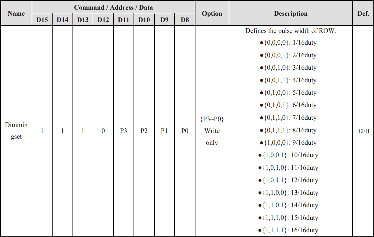
The register has four relevant bits, P0 through P3, in positions D8 through D11. These bits are used to set the duty cycle of the display, which allows for fine control of brightness. By sending the command 1110 1111 (0xEF in hexadecimal), maximum brightness is selected.
Set Blinking Register
The blinking frequency and display state is managed by register 0x80:
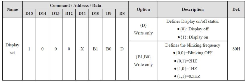
There are three relevant bits in this register: D, B0, and B1 in positions D8 through D10. By sending the command 1000 0001 (0x81 in hexadecimal), the display will be turned on, and blinking will be set to off.
Display Steps
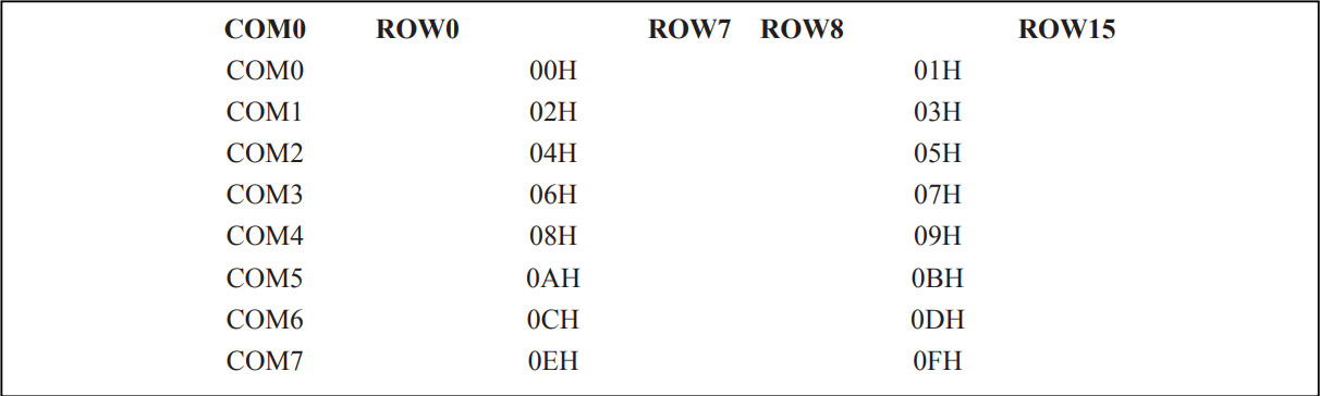
Set the Write Address
The display RAM is 16 bytes and begins at address 0x00:
Send Data to Display
The VK16K33 datasheet explains how the sent data translates into certain segments being activated. This is outside the scope of this project, so for the sake of simplicity, we will skip the conversion. A full code sample is provided later in this project and can be reviewed for more information.
Turn On Display
The display was previously turned on during the Power On Steps, so this step can be ignored.
Testing in the Phidget Control Panel
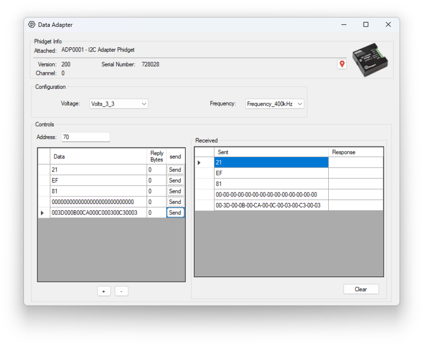
Now that we have the configuration parameters and the command sequence, we can use the Phidget Control Panel to confirm our device is working as expected.
Power On Steps
We can set the voltage to 3.3V, the frequency to 400kHz, and the address to 0x70. We can then queue up the commands we determined in the previous step.
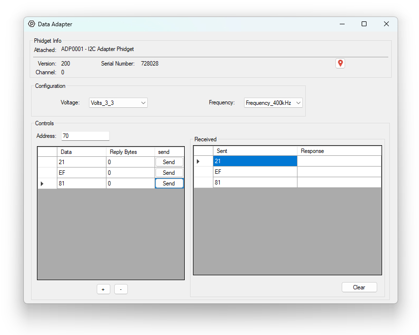
Since we have not sent any data to the RAM yet, the segments are uninitialized, with some on and some off:
Display Steps
To make the screen display PHID, we will first clear the screen with the following command:
- 0x0000000000000000000000000000.
We can then send the following data:
- 0x003D000B00CA000C000300C30003
We can now see the expected result:
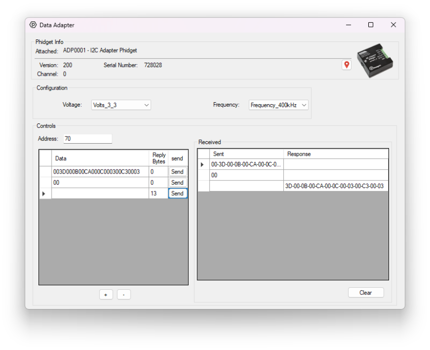
Reading Display RAM
This display also supports reading the RAM, so you can programmatically know what's currently showing on the display. For most devices, this is as simple as providing the proper command and specifying a number of expected reply bytes. In this case, the device is expecting a stop condition in between the command and the data, as shown by the 'P' in the third block in this diagram:
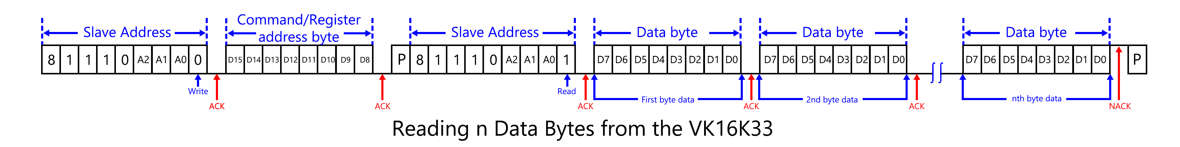
In order to replicate this in the control panel, we must send 0x00 first, and then send again with no data to listen for our reply bytes.
Writing a Custom Python Script
To begin writing a custom program for your Phidget device, navigate to the product page and select the Code Samples tab. From there, you can customize the code for your own purposes. Here we have modified the code sample to match our steps from the Phidget Control Panel.
from Phidget22.Phidget import *
from Phidget22.Devices.DataAdapter import *

def main():


    clear = [0x00,0x00,0x00,0x00,0x00,0x00,0x00,0x00,0x00,0x00,0x00,0x00,0x00,0x00]
    phid = [0x00,0x3D,0x00,0x0B,0x00,0xCA,0x00,0x0C,0x00,0x03,0x00,0xC3,0x00,0x03]


    adp = DataAdapter()
    adp.openWaitForAttachment(5000)


    # Set properties
    adp.setFrequency(DataAdapterFrequency.FREQUENCY_400kHz)
    adp.setDataAdapterVoltage(DataAdapterVoltage.DATAADAPTER_VOLTAGE_3_3V)
    addr = 0x70


    # Clear Screen
    adp.i2cSendReceive(addr, clear, 0)


    # Initialize display
    adp.i2cSendReceive(addr, [0x21], 0)
    adp.i2cSendReceive(addr, [0xEF], 0)
    adp.i2cSendReceive(addr, [0x81], 0)


    # Print PHID
    adp.i2cSendReceive(addr, phid, 0)


    try:
        input("Press Enter to Stop\n")
    except (Exception, KeyboardInterrupt):
        pass


    adp.close()


main()
That’s about it, we went from reading the datasheet to a working script. Not all datasheets are created equal, so if you’re struggling with getting your sensor set up, feel free to ask for help by sending us an email.
Full Script
Here is the full Python script that was used in the demonstration video. It will take input from the console and print scrolling messages on the display.
from Phidget22.Phidget import *
from Phidget22.Devices.DataAdapter import *
import time

ram = ["0000","0000","0000","0000","0000","0000","0000","0000","0000","0000","0000","0000","0000","0000","0000","0000","0000","0000","0000","0000","0000","0000","0000","0000","0000","0000"]

#   _ _ _ b _ _ _
# | \     |     / |
# |  c    e    g  |
# l   \   |   /   d
# |    \  |  /    |
# | _ n _ _ _ a _ |
# |    /  |  \    |
# j   /   |   \   f
# |  m    k    i  |
# | /     |     \ |
# | _ _ _ h _ _ _ |


letters = {
	#      abcdefghijklmn         abcdefghijklmn         abcdefghijklmn
	"A": 0b11010100010101, "N": 0b00110100110100, "0": 0b01010111010110,
	"B": 0b11011101001001, "O": 0b01010101010100, "1": 0b00010110000000,
	"C": 0b01000001010100, "P": 0b11010000010101, "2": 0b11010001010001,
	"D": 0b01011101001000, "Q": 0b01010101110100, "3": 0b11010101000001,
	"E": 0b11000001010101, "R": 0b11010000110101, "4": 0b10010100000101,
	"F": 0b11000000010101, "S": 0b11100101000000, "5": 0b11000101000101,
	"G": 0b11000101010100, "T": 0b01001000001000, "6": 0b11000101010101,
	"H": 0b10010100010101, "U": 0b00010101010100, "7": 0b01010100000000,
	"I": 0b01001001001000, "V": 0b00000010010110, "8": 0b11010101010101,
	"J": 0b00010101010000, "W": 0b00010100110110, "9": 0b11010100000101,
	"K": 0b00000010110101, "X": 0b00100010100010,
	"L": 0b00000001010100, "Y": 0b00100010001000,
	"M": 0b00110110010100, "Z": 0b01000011000010
}

# loadRAM Reads all 13 bytes of of the screen memory into an array of 26 strings (for easier debugging)
# It should be loaded before overwriting a character, to preserve the other three.
def loadRAM(phid, addr):
	for i in range(13):
		byte = format(phid.i2cSendReceive(addr,[i],1)[0],'08b')
		ram[(i*2)] = byte[:4]
		ram[(i*2)+1] = byte[4:]

# printMessage prints a scrolling marquee messasge 'str'
def printMessage(str, phid, addr):
	# Add four spaces to ensure the message scrolls off
	str += "    "
	a0 = a1 = a2 = a3 = ""

	for a in str:
		a0 = a1
		a1 = a2
		a2 = a3
		a3 = a.upper()
		clearScreen(phid,addr)
		printLetter(a0, phid, addr, 0)
		printLetter(a1, phid, addr, 1)
		printLetter(a2, phid, addr, 2)
		printLetter(a3, phid, addr, 3)
		time.sleep(0.08)

# printLetter prints letter 'a' to position 'pos'
def printLetter(a, phid, addr,pos):

	# Confirm parameters are valid
	if a not in letters or (pos > 3) or (pos < 0):
		return

	# Get the segments required for the letter
	bits = [(letters[a] >> bit) & 1 for bit in range(13,-1,-1)]

	# For each segment, AND or OR it to the existing memory to preseve the other three digits
	# It had to be broken into two in order to skip over other bytes in the memory string.
	# The memory string is laid out like this: 00ab0:cd0.ef00gh00ij00kl00mn
	# Where ':' turns on the center colon and '.' turns on the decimal point when 0001 is written there.
	for i in range(7):
		if bits[2*i] == 0:
			tmp = int(ram[4*i], 2)
			tmp &= ~(1 << pos)
			ram[4*i] = f"{tmp:04b}"
		else:
			tmp = int(ram[4*i], 2)
			tmp |= (1 << pos)
			ram[4*i] = f"{tmp:04b}"

		if bits[(2*i)+1] == 0:
			tmp = int(ram[(4*i)+1], 2)
			tmp &= ~(1 << pos)
			ram[(4*i)+1] = f"{tmp:04b}"
		else:
			tmp = int(ram[(4*i)+1], 2)
			tmp |= (1 << pos)
			ram[(4*i)+1] = f"{tmp:04b}"

	hex = bytes(
		(int(ram[i], 2) << 4) | int(ram[i+1], 2)
		for i in range(0, 26, 2)
	)
	hex = list(hex)
	hex.insert(0,0x00) # add the leading 0x00 for writing
	phid.i2cSendReceive(addr, hex, 0)

# clearScreen clears the screen and the ram array
def clearScreen(phid,addr):
	phid.i2cSendReceive(addr, [0x00,0x00,0x00,0x00,0x00,0x00,0x00,0x00,0x00,0x00,0x00,0x00,0x00,0x00], 0)
	loadRAM(phid,addr)

# initialize sets the clock, brightness and blinking so the screen can operate
def initialize(phid,addr):
	phid.i2cSendReceive(addr, [0x21], 0)
	phid.i2cSendReceive(addr, [0xEF], 0)
	phid.i2cSendReceive(addr, [0x81], 0)

def main():

	# Declare and open dataAdapter channel
	adp = DataAdapter()
	adp.openWaitForAttachment(5000)

	# Set properties
	adp.setFrequency(DataAdapterFrequency.FREQUENCY_400kHz)
	adp.setDataAdapterVoltage(DataAdapterVoltage.DATAADAPTER_VOLTAGE_3_3V)
	addr = 0x70

	# Clear Screen
	clearScreen(adp,addr)

	# Initialize display
	initialize(adp,addr)

	print("Type a message to display, or 'exit' to quit.")

	message = ""

	while message != "exit":
		try:
			message = input()
			printMessage(message,adp,addr)
		except (Exception, KeyboardInterrupt):
			pass

	adp.close()

main()