|
Notice: This page contains information for the legacy Phidget21 Library. Phidget21 is out of support. Bugfixes may be considered on a case by case basis. Phidget21 does not support VINT Phidgets, or new USB Phidgets released after 2020. We maintain a selection of legacy devices for sale that are supported in Phidget21. We recommend that new projects be developed against the Phidget22 Library.
|
Uncategorized files
Showing below up to 50 results in range #1 to #50.
- 1002.jpg 400 × 303; 28 KB
- 1002 0 Analog Screen.jpg 662 × 1,067; 250 KB
- 1002 0 Connecting the Hardware.jpg 866 × 365; 106 KB
- 1002 0 Control Panel Screen.jpg 929 × 537; 217 KB
- 1002 0 Under.jpg 1,920 × 1,408; 347 KB
- 1002 hw start.png 1,128 × 446; 274 KB
- 1010.jpg 400 × 279; 23 KB
- 1010 0 Advanced Sensor Screen.jpg 1,475 × 979; 383 KB
- 1010 0 Connecting The Hardware.jpg 925 × 687; 403 KB
- 1010 0 Control Panel Screen.jpg 865 × 523; 209 KB
- 1010 0 InterfaceKit Screen.jpg 1,337 × 733; 327 KB
- 1010 0 PinOut.jpg 616 × 776; 252 KB
- 1010 EUE P1 0.pdf ; 47 KB
- 1011.jpg 400 × 268; 12 KB
- 1011 0 Advanced Sensor Screen.jpg 1,475 × 979; 412 KB
- 1011 0 Connecting The Hardware.jpg 1,150 × 729; 276 KB
- 1011 0 Connector Diagram.jpg 1,135 × 403; 209 KB
- 1011 0 Control Panel Screen.jpg 933 × 519; 204 KB
- 1011 0 InterfaceKit Screen.jpg 1,337 × 733; 295 KB
- 1011 0 Wire Assembly.jpg 1,500 × 820; 451 KB
- 1012.jpg 400 × 330; 45 KB
- 1012 2 Connecting The Hardware.jpg 1,156 × 740; 350 KB
- 1012 2 Control Panel Screen.jpg 929 × 537; 211 KB
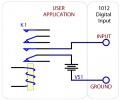
- 1012 2 Digital Inputs 1.jpg 494 × 389; 93 KB
- 1012 2 Digital Inputs 2.jpg 336 × 385; 68 KB
- 1012 2 Digital Inputs 3.jpg 460 × 385; 78 KB
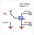
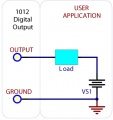
- 1012 2 Digital Outputs 1.jpg 372 × 385; 69 KB
- 1012 2 Digital Outputs 2.jpg 360 × 381; 69 KB
- 1012 2 InterfaceKit Screen.jpg 1,337 × 740; 308 KB
- 1014.jpg 400 × 284; 36 KB
- 1014 1 Bridge Diagram.jpg 1,250 × 784; 118 KB
- 1014 2 Connecting The Hardware.jpg 889 × 425; 162 KB
- 1014 2 Control Panel Screen.jpg 929 × 537; 209 KB
- 1014 2 InterfaceKit Screen.jpg 1,337 × 733; 250 KB
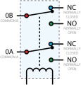
- 1014 2 Relay Diagram.jpg 454 × 273; 59 KB
- 1015.jpg 400 × 137; 20 KB
- 1015 0 Connecting The Hardware.jpg 963 × 315; 126 KB
- 1015 0 Control Panel Screen.jpg 885 × 500; 193 KB
- 1015 0 InterfaceKit Screen.jpg 1,337 × 740; 262 KB
- 1015 0 Manager Screen.jpg 854 × 421; 179 KB
- 1016.jpg 400 × 295; 39 KB
- 1016 0 Connecting The Hardware.jpg 917 × 490; 164 KB
- 1016 0 Control Panel Screen.jpg 856 × 494; 193 KB
- 1016 0 InterfaceKit Screen.jpg 1,337 × 740; 264 KB
- 1016 0 Manager Screen.jpg 854 × 421; 180 KB
- 1017.jpg 400 × 266; 38 KB
- 1017 1 Connecting The Hardware.jpg 801 × 539; 224 KB
- 1017 1 Control Panel Screen.jpg 919 × 517; 205 KB
- 1017 1 InterfaceKit Screen.jpg 1,337 × 733; 257 KB
- 1017 1 Relay Diagram.jpg 467 × 489; 101 KB


